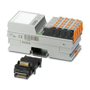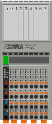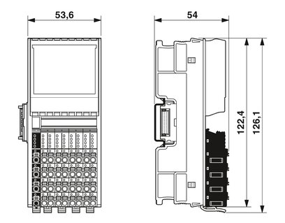


The module is designed for use within an Axioline F station. It is used to acquire signals from resistive temperature sensors. The module supports all common platinum and nickel sensors in accordance with DIN EN 60751 and SAMA. Cu10, Cu50, Cu53 sensors as well as various KTY8x sensor types are also supported.
Category:PLC
Discover unparalleled temperature sensing capabilities with the AXL F RTD8 XC 1F Module by Advanced Navigation. This advanced module sets the standard for precision temperature measurement, offering reliability and accuracy for diverse applications. Elevate your temperature sensing requirements to new heights with the cutting-edge technology of AXL F RTD8 XC 1F Module.
Your advantages 8 analog input channels for the connection of resistance temperature detectors (RTD) 500 Ω and 5 kΩ linear inputs Connection of sensors in 2-, 3-, and 4-conductor technology Integrated, digital sensor linearization Standardized measured value representation directly in °C, °F or Ω Measured value display in 16-bit format or floating point format Programmable filters Short-circuit protected inputs Temperature stability Very high level of noise immunity AXL F RTD8 1F Low noise emission Installation monitoring by means of “Channel scout” function Can be used under extreme ambient conditions Extended temperature range of -40 °C … +70 °C (see “Tested successfully: use under extreme ambient conditions” in the data sheet) Partially coated PCBs Device rating plate stored AXL F RTD8 1F
| Potentials | |
| Power consumption | typ. 0.94 W (at UBus and UA (up to HW 01)) |
| typ. 0.59 W (at UBus and UA (from HW 02)) | |
| max. 1.5 W (at UBus and UA (up to HW 01)) | |
| max. 1.03 W (at UBus and UA (from HW 02)) | |
| Potentials: Axioline F local bus supply (UBus) | |
| Supply voltage | 5 V DC (via bus base module) |
| Current draw | max. 180 mA (up to HW 01) |
| max. 85 mA (from HW 02) | |
| typ. 115 mA (up to HW 01) | |
| typ. 60 mA (from HW 02) | |
| Power consumption | max. 900 mW (up to HW 01) |
| max. 425 mW (from HW 02) | |
| typ. 580 mW (up to HW 01) | |
| typ. 300 mW (from HW 02) | |
| Potentials: Supply for analog modules (UA) | |
| Supply voltage | 24 V DC |
| Supply voltage range | 19.2 V DC … 30 V DC (including all tolerances, including ripple) |
| Current draw | max. 25 mA |
| typ. 15 mA (up to HW 01) | |
| typ. 12 mA (from HW 02) | |
| Power consumption | max. 0.6 W |
| Protective circuit | Surge protection; electronic (35 V, 0.5 s) |
| Reverse polarity protection; Polarity protection diode | |
| Transient protection; Suppressor diode | |
| Electrical isolation/isolation of the voltage ranges | |
| Test voltage: 5 V supply of the local bus (UBus) / 24 V supply (I/Os) | 500 V AC, 50 Hz, 1 min. |
| Test voltage: 5 V supply of the local bus (UBus)/analog inputs | 500 V AC, 50 Hz, 1 min. |
| Test voltage: 5 V supply of the local bus (UBus) / functional ground | 500 V AC, 50 Hz, 1 min. |
| Test voltage: 24 V supply (I/O)/analog inputs | 500 V AC, 50 Hz, 1 min. |
| Test voltage: 24 V supply (I/O) / functional ground | 500 V AC, 50 Hz, 1 min. |
| Test voltage: Analog inputs/functional ground | 500 V AC, 50 Hz, 1 min. |